Introduction to Antminer L7 Hash Board Repair
This comprehensive guide is designed to provide detailed instructions on how to properly repair and maintain the Antminer L7 hash board, ensuring optimal performance and longevity of your mining equipment.
Preparation and Maintenance Guidelines
This guide provides comprehensive instructions on maintaining an Antminer L7 properly. It covers routine testing, locating faulty chips, re-soldering and replacing parts, making relevant maintenance/analysis records, assembling the machine for aging tests, and more. By following these steps, you can ensure your Antminer L7 runs optimally with minimal downtime.
Preparation Requirements for Repair Platform, Tools, and Equipment
I. Platform Requirements:
- Static repair workbench (grounded)
- Anti-static wristband and grounding
II. Equipment Requirements:
- Soldering Iron:
- Constant temperature soldering iron (350°C - 380°C) with a pointed tip for small patches like chip resistors and capacitors.
- Hot Air Gun and BGA Rework Station:
- Used for chip/BGA disassembly and welding.
- Multimeter:
- Recommended: Fluke 17B+ with welded steel needles and heat-shrinkable sleeves for easy measurement.
- Oscilloscope:
- Network cable required for an internet connection.
III. Test Tool Requirements:
- APW12 Power Supply:
- APW12_14V-17V_V1.2 and power adapter cable for hash board power supply.
- Test Fixture:
- Material number ZJ0001000001. The positive and negative poles need discharge resistors (recommended: 20 ohms, 100W or more cement resistance).
IV. Maintenance Auxiliary Materials/Tools Requirements:
- Solder paste M705, flux, board washing water, and anhydrous alcohol.
- Board washing water for cleaning flux residue.
- Thermally conductive gel (Fujipoly SPG-30B) for applying on the chip surface after repair.
- Ball-planting steel mesh, solder-absorbing wire, and solder balls (recommended diameter: 0.4mm).
- When replacing a chip, tin the chip pins before soldering to the hash board. Apply thermal conductive gel evenly on the chip surface and lock the heat sink.
- Serial port code scanner.
- Serial port adapter board RS232/TTL adapter board 3.3V.
- Self-made short-circuit probe (pins wired and soldered, heat shrinkable sleeve to prevent short-circuit).
V. Common Maintenance Spare Material Requirements:
- 0402 Resistor (0R, 1K, 4.7K, 10K)
- 0402 Capacitor (0.1uF, 1uF)
Maintenance Requirements
- Chip Replacement:
- Pay attention to the operation method. After replacing components, check the PCB board for deformation, missing parts, open circuits, and short circuits.
- Personnel Requirements:
- Maintenance personnel must have electronic knowledge, over one year of maintenance experience, and proficiency in BGA/QFN/LGA packaging and welding technology.
- Testing:
- Test the hash board at least twice, ensuring all tests pass before final approval.
- Tool and Test Fixture Checks:
- Ensure tools and test fixtures function normally. Determine parameters for maintenance station test software and test jig version.
- Functional Test for Chip Replacement:
- Test the chip first, then conduct a functional test after passing. Ensure small heatsink welding is OK, the large heatsink is installed correctly, and thermal adhesive gel is applied evenly. Use fans to dissipate heat and ensure full speed.
- Power Supply Connection Order:
- When powering the hash board, connect the negative copper wire first, then the positive copper wire, and finally the signal cable. Reverse the order when disassembling to prevent damage.
- Chip Soldering:
- Tin the chip pins before soldering to the PCBA for maintenance.
Overview of Antminer L7 Components
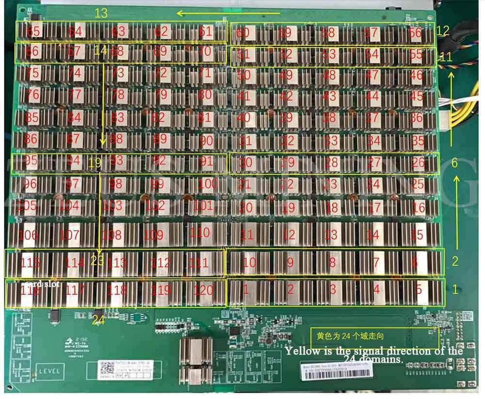
L7 Hashboard Structure:
- Composed of 120 BM1489 chips, divided into 24 domains, each with 5 ASIC chips. The working voltage is 0.6V.
Boost Circuit:
- Converts the 15V power supply to 19.6V.
Signal Direction:
- CLK signal flows from the 25M crystal oscillator (Y1 for chips 1-60, Y2 for chips 61-120).
- RST and CI signals flow from the IO port 3 pin (3.3V) to the level conversion ICs, then from chip 01 to chip 120.
- RX signal flows from chip 120 to chip 01.
- BO signal flows from chip 01 to chip 120.
Antminer L7 Structure:
- Consists of three hash boards, one control board, an APW12 power supply, and four cooling fans.
Identifying Common Issues with Hash Boards and Troubleshooting Procedures
Phenomenon 1: Chip Detection Issues
- Check power supply output and domain voltage.
- Verify PIC circuit output (around 3.2V).
- Check boost circuit output (23V on C70).
- Inspect LDO output (1.8V or PLL 0.8V).
- Measure chip signal output voltages.
Phenomenon 2: Single-Board Detection Failure
- Measure total domain voltage and boost circuit voltage.
- Short-circuit RO and 1V8 test points to isolate the faulty chip.
- Check LDO circuits, U1 and U2 circuits, and chip pins for proper soldering.
Phenomenon 3: Single Board Pattern NG
- Replace the affected chip with the lowest reply rate in each domain.
Phenomenon 4: P
- (Poor Reply Rate)Check and replace the chips with the lowest reply rate.
Phenomenon 5: Sensor NG
- Check the temperature sensor circuit and power supply (3.3V on the 8th pin).
- Maintain the PT2 test environment temperature between 25℃ and 30℃.
Troubleshooting Common Miner Failures
Preliminary Test of the Whole Machine:
- Check for assembly and control board process problems, such as IP detection, fan count, and detected chains.
Aging Testing of the Miner:
- Address issues like abnormal fan display, missing chains, high temperature, and insufficient chips.
- Reduce frequency if hash rate issues persist and measure domain voltage and RI signal.
Other Considerations and Maintenance Flow Chart
- Routine Testing:
- Inspect the hash board for deformities, burn marks, short circuits, open circuits, and domain voltage.
- Chip Test Points:
- Check CI/NRST/RO/XIN/BI and voltages of VDD 0V8 and VDD 1V8.
- Signal Flow Trace:
- Locate unusual points of failure.
- Chip Re-soldering:
- Apply flux, heat solder joints, re-tin chip pins and pads. Replace the chip if necessary.
- Testing:
- Conduct at least two tests, allowing the hash board to cool down between tests.
- Record Keeping:
- Maintain records for production, after-sales, and research purposes.
- Assemble and Age Test:
- Assemble the hash board and conduct routine aging tests.
By following these guidelines, you can ensure proper maintenance and optimal performance of your Antminer L7.